The ongoing demand for high-performance solar panels at a reasonable cost makes solar companies experiment with the structure of solar cells and tweak the module design. To improve the efficiency of the overall module, solar manufacturers optimize not just the solar cell but its entire cell design. One of such modifications or new innovations is incorporating multiple busbars on a panel.
What is the busbar?
In the solar cell, there is a thin rectangular strip printed on front and backside of the solar cell to conduct electricity, that strip is called a busbar. The purpose of the busbar is simple yet crucial as it separates the cells to conduct direct current from the photons and transfer it to the solar inverter to convert the current into alternating current. The busbars are generally made of copper plated with silver(Ag) paste to enhance the current conductivity in the front side and to minimize the oxidation at the backside. Similarly, multiple busbars are used to wire solar cells together to generate high voltage electricity.
A panel with multiple busbars ensures high cost-saving potential as the metallization process will need less amount of silver coating on the front side. Metallization plays a significant role in the fabrication of PV solar cells because the silver coating for deposition of fingers and buses is one of the most expensive steps in cell fabrication. Multi busbar can aid in decreasing the total series resistance of the interconnected solar cells.

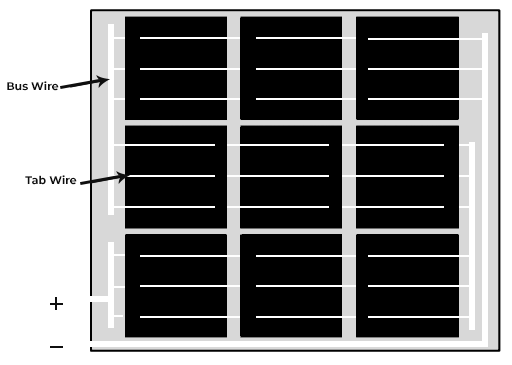
Perpendicular to busbars is the metallic and thin grid finger. The fingers aid in the collection of generated current to the busbars. The cumulative power collected by all the busbars with the parallel tab wired cell strings (ribbons) is then delivered to the junction box. A solar cell grid consists of these thin current-collecting/current-delivering fingers and the current-conducting busbars. The key to efficient solar panel design is to strike an optimum balance between the busbar and the resistance/ shading/ reflection losses of fingers.

How do multiple busbars work?
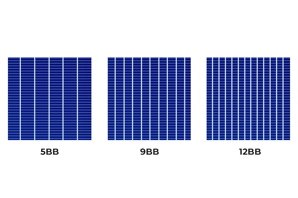
Nowadays, multi busbar cells have become standard in solar panel design. The minimum number of busbars has increased to 9BB from conventional 2BB. Several manufacturers have intensified their efforts a step further and designing 10BB to 12BB panels. They are focusing on designing panels using PERC (Passivated Emitter Rear Contact) cells with a maximum number of busbars in frontside contacts. Multi busbars aid in the reduction of internal resistance losses, which occur due to the shorter distance between the busbars.

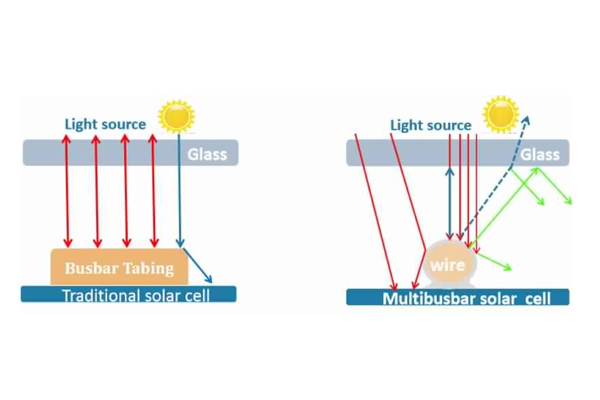
In a typical solar cell, the metallization pattern usually has thin silver fingers that are responsible for current collection and transportation to the thick busbars. These busbars are then connected to the ribbons (cell strings coated with copper wires) in the photovoltaic module design. The increase in the number of busbars minimizes the current in each ribbon and hence lessens the resistive losses.
Additionally, the distance that the current has to travel from collection fingers to the busbar is plummeted further reducing the resistance of the solar cell and consequently the losses. This allows curtailing the usage of silver paste – as it is the costliest consumables for a silicon wafer.
The usage of multiple numbers of busbars also saves the panel from microcracking. Micro-cracks generally happen between busbars, the effect of these cracks is thus diminished towards smaller affected cell slices between two busbars. Therefore, if we compare the conventional counterpart modules with 2BB and 3BB cells, the long-term durability and reliability of multi-bus bars in case of micro-cracks are commonly higher.

Dash-line pattern busbars
Solar manufacturers never stop researching and innovating new module designs to cut the production costs and to increase efficiency. One of such recent inventions is panels with dash-line pattern busbars, it reduces the usage of expensive silver paste. These modules are available with 3-dash, 5-dash, 6-dash and even 8-dash busbars.
Studies have shown that these panels are more sensitive, meaning they are prone to cracking and power degradation. Increased number of dash lines cause the accumulation of thermal stress in the panel which result in cracking at the corners of the busbar.


All things considered
In conclusion, the goal of using multi busbar cells is to reduce the resistive losses by minimizing the flow of current in both fingers and the busbars. It has the potential to decrease the silver paste usage by 50-80%, less amount of silver also helps in eliminating the finger shading as well. It also enhances the efficiency of cell performance.